|
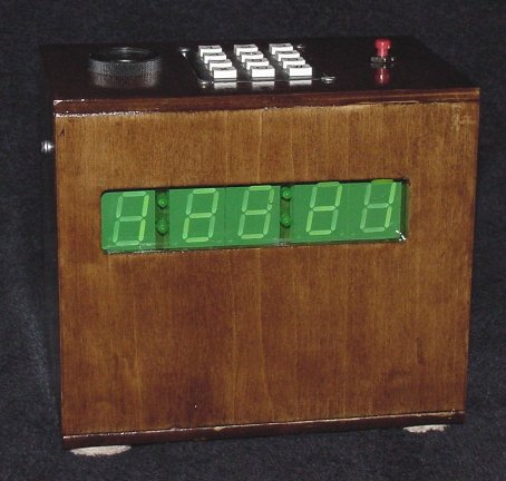
The project requirements were as follows. The kitchen timer had to be
easily set to count down hours, minutes, and seconds, with a lighted
display, and a very loud buzzer when it reached zero. The buzzer had
to be loud enough to hear at the other end of the house from the kitchen.
The timer must turn itself off after the buzzer completes its buzzing,
or after 15 seconds of inactivity.
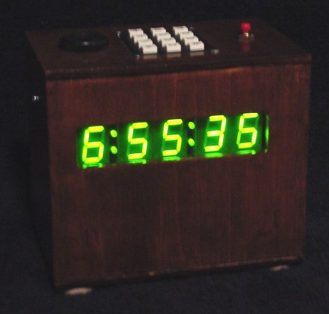
Seconds were added to the design on the fly just because I wanted them
there. In all, the timer can count up to 9 hours, 99 minutes, and 99 seconds
in any one sitting.
|

|
|

|
All circuit boards were to be designed and etched from scratch by me.
By "from scratch" I don't mean mining ore, smelting copper, and doping
layers of silicon (although *THAT* would certainly be impressive!).
I mean etching a PCB and plugging in whatever components were necessary.
|
|
|
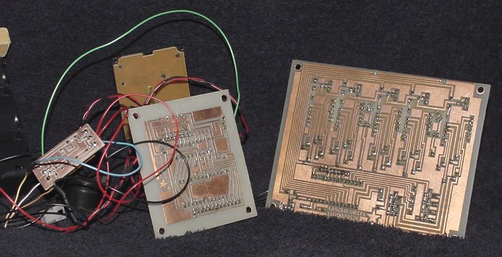
The printed circuit boards were drafted manually in Paint Shop Pro.
The layouts were applied to the copper clad board by way of
the laser-printer-iron-on technique and etched using
FeCl3 (ferric chloride - the generic stuff
you get from any electronics outlet).
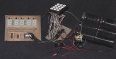
In an attempt to make things as
modular as possible, I ended up with three seperate PCBs. From left
to right, this picture shows the power control system, the CPU board,
and the display board.
|
|
|
|
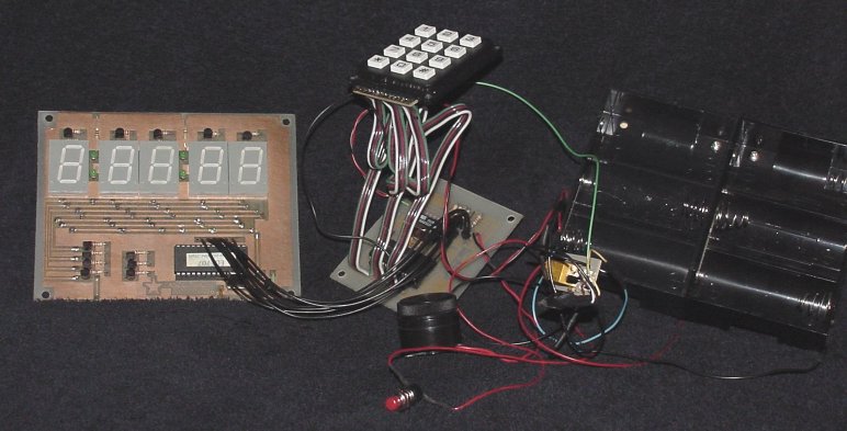
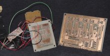
Here are the component sides of the PCBs. The display board (left) holds
an EDE707 8-digit 7-segment LED driver chip. This does the job of
holding and displaying the digits as commanded by the CPU.
The CPU board is in the middle there, behind the mess of
wires (thick, unruly wires because that's what I had on hand). The CPU
itself is an Atmel AT90S2313-10PC. I coded the input, clock, and
output code completely from scratch in Atmel's AVR assembly.
In order
to write the program to the CPU I had to design and build a programmer
and its associated PC-based software (that's a whole seperate project).
|
|
|
I would have much preferred to put this in a metal project box. However,
I don't have a brake or sheer, so I am unable to work with sheet metal at
this time. Clear polycarbonate was my second choice, but at $35 it was
cost prohibitive. Enter basswood. It's not very strong, but it'll do as long as
nobody drops it on the floor. I used the Sherline vertical mill to
route out the edges of the 3/16 inch basswood.
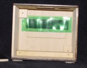
I wanted a tinted window
to enhance the appearance of the green LED display when the kitchen light
was on. For this I used two layers of plastic from a green soda bottle,
glued together with a
hot glue gun (clear proof that your humble narrator embodies the pinnacle,
the acme, the zenith of high-tech).
|
|
|
|
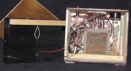
Not everything is screwed onto something, but those thick wires (plus a
little card stock for safety) makes for a snug fit anyway. This was a
big plus, considering that I effectively made *NO* plans for how things
would fit in the case while I was laying out the PCBs (although I did
at least design screw holes in at the corners).
Yes! I *KNOW* it's a mess! Wires, wires everywhere! If you knew the story
of how long I procrastinated on this project, you would understand why, in this case,
screwing it together and getting it OFF of my to-do list, was far, far, far more
important than trimming the farkin' wires to fit the dad-blast-it case!
|
|
|
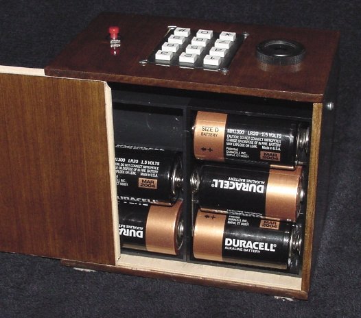
Completely assembled, the rear panel slides easily into place. Yes, those
are "D" cells, five of them. The "D" cell decision was made for several
reasons. There was never a power efficiency requirement (too much learning
curve for this project). I abhor wall warts; All our outlets are in use,
and I wanted it to be somewhat movable. Finally, I wanted to be comfortable
with someone timing a 7-hour turkey with at least a reduced likelihood of
the 7th hour lasting 3 hours and causing a bad case of birdburn.
|

|
|
Instructions For use
- Press the red button to turn on the power.
- Enter the desired hours, minutes, and seconds.
(e.g. "40" is forty seconds, "4000" is forty minutes, "40000" is four hours)
- Press the "#" (pound) key to begin the countdown.
- The "*" (asterisk) key will reset the counter to zero at any time, including
while the buzzer is sounding.
- While waiting for input, if you do nothing for 15 seconds, the timer
will shut itself off.
|
|
|
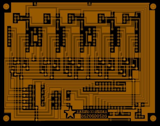
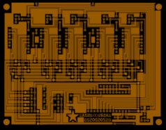
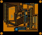
These images are flattened into JPGs. They're not meant to be useful, just
neat to look at. If someone REALLY wants my PCB layout images [seperated]
I'll consider it.
|
PCB layout
for display board.
|
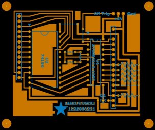
PCB layout
for CPU board.
|
|
|
|